Building my own line-following robot won’t be so hard, right?
Hello, my name is Mario, and in my journey to learn about the amazing area that is robotics I decided that to start it would be a good idea to create a line following robot. It is a simple robot, with few sensors and a simple task to accomplish: follow a line. But as I started to plan, research, design and build the robot, it turned out to be more and more complex, because of two things that I didn’t took in consideration: my lack of knowledge on many steps of the process and my incredible passion for doing it all by myself.
I come from a computer science background, so I have a lot of coding experience and some IA knowledge, but in robotics, this is only a few pieces of the puzzle. I took a class that was more focused on the coding and algorithm part of the field, so I wanted to at least get a small intro to every other aspect of the field. I read some tutorials and gathered the info that I needed as a guidance, but I wanted to work on every step to change things to made them my own, and to use this project to learn new things, like using some of my old and small Arduino knowledge or learning to use CAD software to design the robot. This made everything harder than just following a tutorial, and much longer times for almost every task, but I’ve learn many things and enjoyed every step of the project.
On my head, the process would be easy and smooth, something like this:
-
Get the idea of the robot
-
Design the robot
-
Decide electronics and sensors
-
Design the chasis
-
3D print the chasis
-
Assemble the robot
-
Code
-
Test and calibrate
But what really happened was something like this:
-
Get the general idea of what the robot does
-
Read and research how people usually build this robot
-
Try to design my own, which implied to decide:
-
Electronic and sensors
-
How to arrange everything
-
How I will fit everything on the chasis
-
-
Bought the required components
-
Tested the electronics
-
Design the chasis, which took me much more time because I thought that learning CAD won’t took me that much time (it did)
-
Realized that there were parts missing, so had to buy more things and wait for them
-
A package with some parts got lost, bought new ones
-
Realized that some of the parts where wrong, so had to modify/adapt them
-
Use my 3D printer to print the chasis parts
-
See my prints fail and spend time fixing the printer
-
Actually fit everything
-
Code
-
Test, calibrate, modify, repeat
So, not as smooth and easy as I thought it will be.
Let’s go step by step and see in more details what happened, why, how and what I’ve learn in this journey.
Designing the robot
The idea is simple. You put the robot on a line, the robot detects the line and follows the line. The line is built using black tape, and when there are some curves the robot has to turn and keep on the line. The color of the line is black, and the floor of my apartment is similar to wood parquet ????. After reading and investigating, the easiest thing to try was to use some IR sensors to detect if we are or not over the line.
IR sensors emit a laser beam which is reflected on the surface of objects and bounces back to a receiver. The time that has happened since the laser was emitted is used to compute the actual distance. However, black surfaces absorbe light, so we don’t actually need to measure the distance but if we are receiving a measurement. On the normal floor, the light will bounce back but on the black tape it won’t.
We can build an array of sensors to check where the line is, and therefore, move our little boy accordingly. On the book “Arduino Robotics” [1] the autor builds it’s own sensor from the emitters and receivers, so I thought that it will be OK to follow how he did it. This book was a great source of ideas. The author also uses servo motors to control the robot, and I decided that I would also do it like that.
The controller that I used was an Arduino because:
-
Lot’s of tutorials and documentation
-
Don’t need heavy computations
-
Already had one
I decided to use a battery holder that I had also as a power source, a servo-hat for controlling the servos and that was almost all for the electronics. Bought the components, bought some screws and waited until all come while I decided how to fit everything together.
First problems and testing electronics
The first problem that happened was that the package of IR sensors-emitters that I bought got lost which, given that I bought it on a cheap store, was something that could have been expected. I decided to look for other sensors and I found and bought what I thought were IR sensors but turned out to be IR proximity sensors. At first I thought that I was an idiot, since those sensors returned a boolean value if there is something near or not, but I tested them and thought of a way to use them:
-
The sensor is calibrated with a potentiometer to decide at which point it will return a true reading. If you calibrate them to return true when there is floor, when there is a piece of black tape the actual light will get absorbed and will not bounce back, therefore returning a false reading. We can use this to then actually measure if we are or not over black tape.
-
This is similar to the sensor built on the book that I read, but the book used the actual values sensed on the receiver to check the thresholds. This is a different approach but is perfect for what we want to accomplish.
I decided then to test the servos and to learn how to control them with the arduino. Servos can be bought typically with a degree of movement, like 90 or 180 degrees of motion, so if you want to use to move the wheels you need to be modify them to actually make them rotate continuously. The servos need to be modified to actually make them rotate continuously, which I did by removing the potentiometer and soldering some resistances to fix the value read b the servo controller. A much better explanation of what and why you need to do to modify them can be found in this video [2]. But, if I had to make the robot again, probably a better idea is to let the manufacturers do their job and buy some continuous rotation servos.
After some testing and re-soldering I made the servos work as intended. I then added a battery holder that I had, a voltage regulator for powering everything up and an on-off switch. After coming up with all the components it was time to decide the actual design and position of the components on the chasis. It was time to learn CAD modeling (spoiler alert: it was not as easy as I thought)
3D modeling the chasis
DISCLAIMER: I have no idea of mechanical design, no idea of any kind of engineering design to be honest. This was done by trial and error, and with the idea that what I thought was somehow decent. It is not perfect, but it is what it is.
I’ve had an Ender 3 Pro for a few weeks before I embarked on this journey of building the robot, but never did a model by myself. I knew that for this kind of application and for designing things as a maker I needed to learn how to use CAD software, so when I was thinking on the full project I thought that this would be the perfect opportunity to do so. I then took a tutorial on Fusion360, thought that it was quite simple to do some of the basic stuff that I needed and went to try to model the chasis.
What happened was that, even though you can get a basic idea of how the program behaves and the tools that you have available, you are not going to actually learn unless you try to do something, like in photoshop. And like in photoshop, what is difficult is to actually find what is the actual process needed. You have some tools, you have an idea of what you want to do but you don’t know what steps you should follow and using which tools because this is learn by doing, it comes with practice. It took me more hours to get to the idea of what I needed to do and how, but I ended with this design:
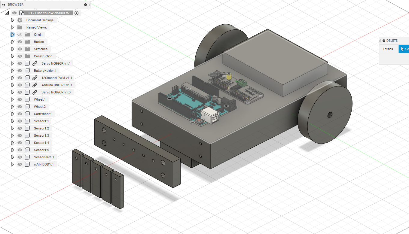
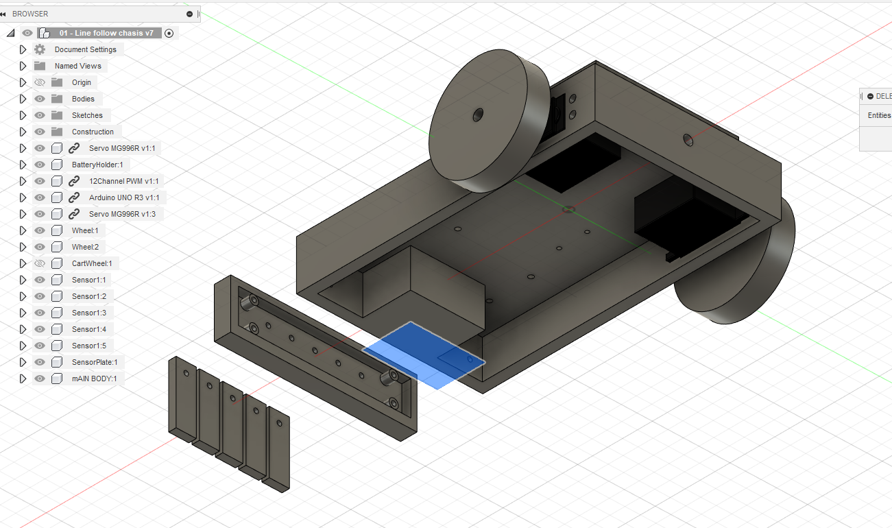
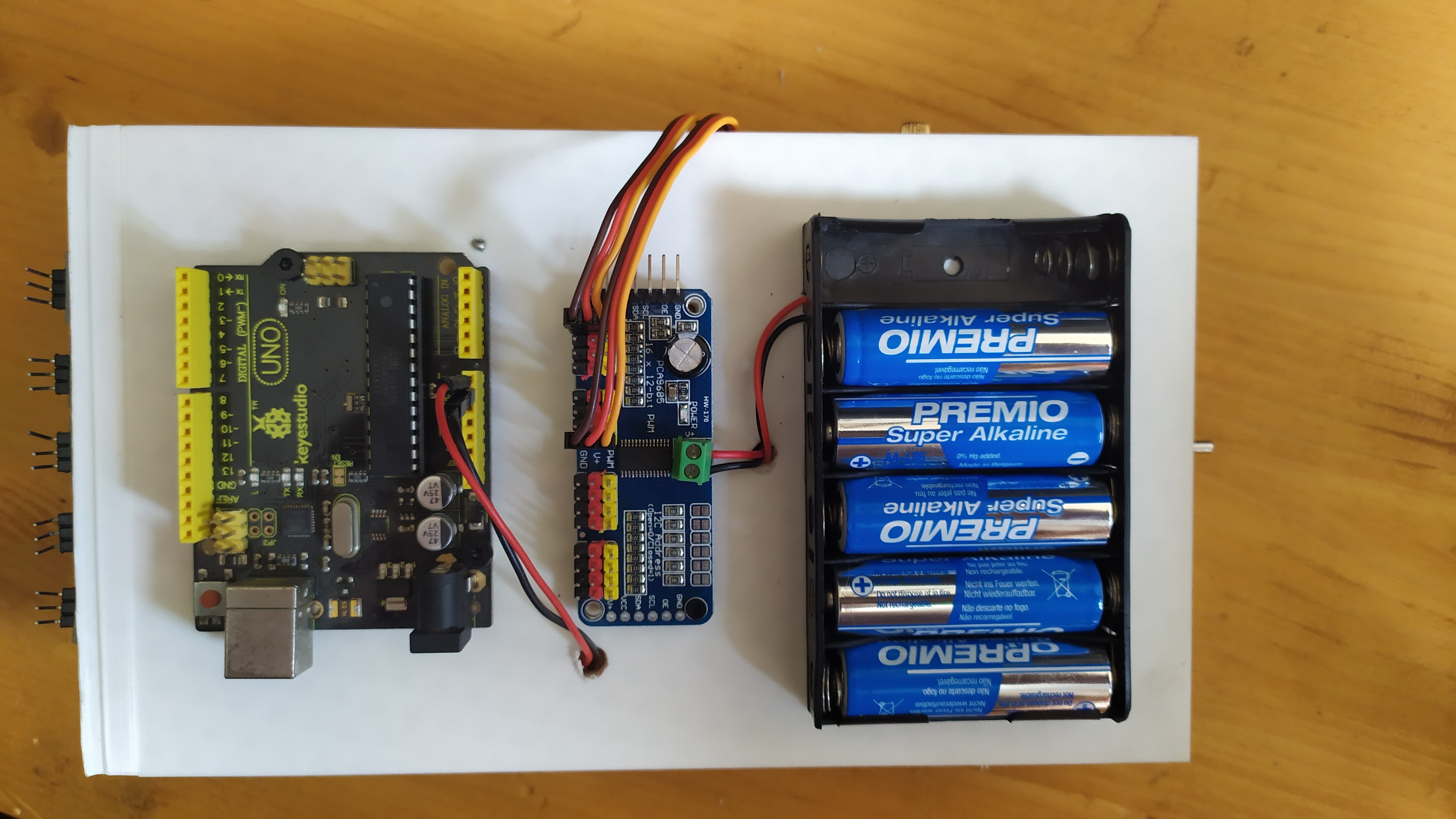
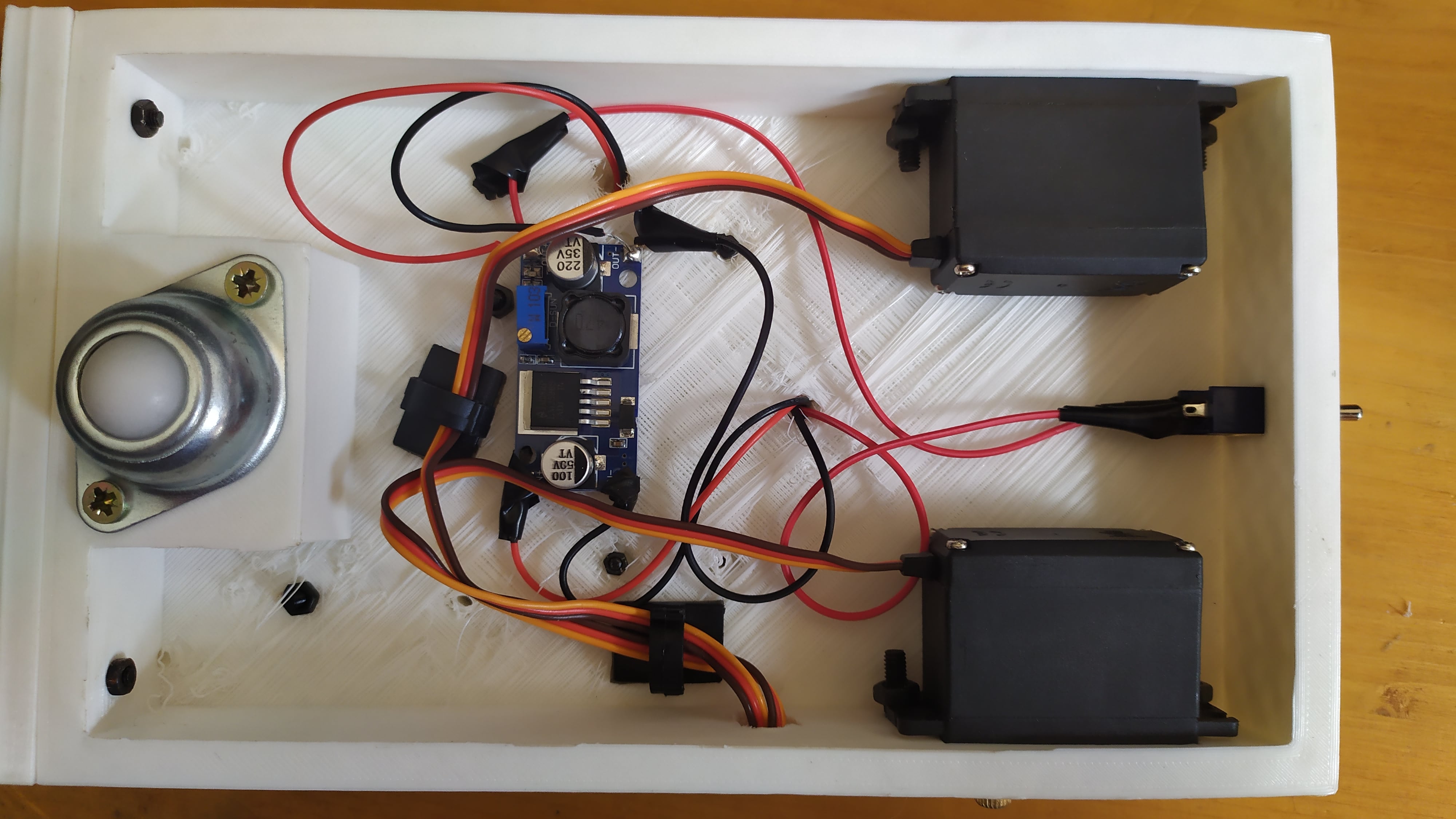
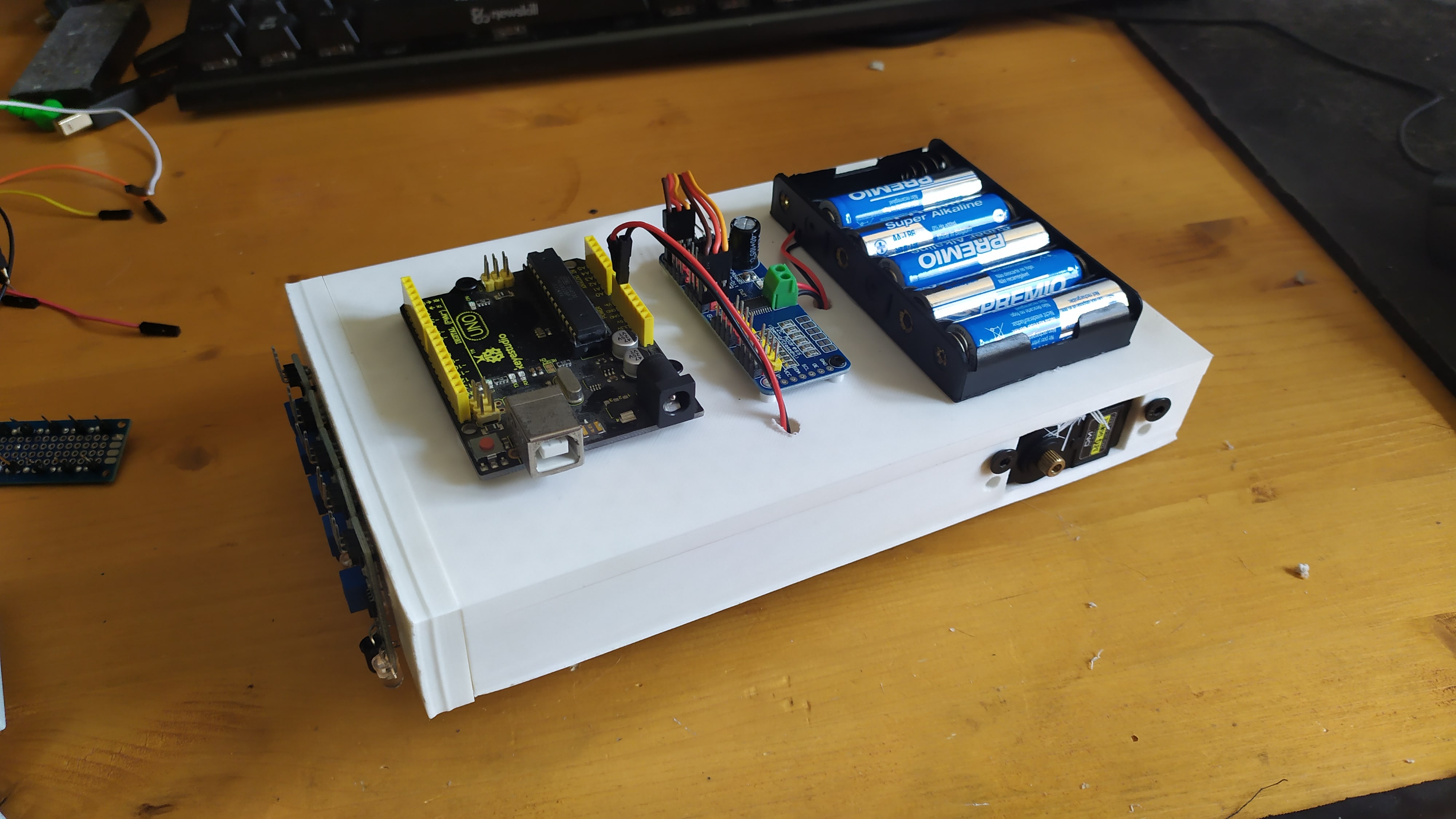
The main body has the servos on the inside, attrached with some screws, a little block in the front for a cart wheel and the arduino, servo shield and batteries on the top part. The front sensor array is attached with some screws and can be removed and change to another one, so if in the future I want to reuse the chasis I can change the sensor plate to another different thing and repurpose almost every other part. The board and bigger parts are on top of the chasis, while the motors are attached by some screws to the sides, with an on/off switch on the back of the robot.
After a few tries and some patience, I printed both parts and started to assemble the robot. Only some minor adjustements had to be made to the chasis, mainly drilling holes to pass cables to the top part, and I assembled the motors, arduino, servo shield to the body and the sensors to the front plate.
Motor testing and calibration
Servos work by receiving a PWM signal, which is translated into the position depending on the length of it (yes, this is very simplified). The library to use the servo shield, since it is built to work with many servos, uses 3 main parameters: the servo attached, from 0 to 15, the address of the board?? (since they can be chain-connected to allow the control of more servos) and the number of ticks that the pulse is extended on time. The duty cycle has a minimum duration to be perceived as one of the extremes of the rotation (-60 for example), a centered one (0 degrees) and a maximum one (60 degrees). Positions in between are estimated using these maximum and minimum positions. For our case, the min/max positions, since they are never reach, will make the servo rotate continuously on one/other direction, making our robot move forward, move backward and rotate on place.
These min/max values have to be defined to properly move the robot. Since I modified the servos, I spent some time calibrating the servo by trying different values to have the minimum, maximum and centered position. I was not convinced on my soldering/modification skills on the servos, so rather than spend time trying to calculate them I decided to use the old-but-useful way of trial and error to get the values. This turned turned out to be a good idea since, as I said, I’m terrible at soldering, and the modifications made the servos have different values for the left and the right servo.
I wrote some functions to help me drive the servos, attached the wheels and then I continued with the next step.
Sensor auxiliar board and calibration
To help with the cable management I made a small board to provide connection between the arduino and the sensors, and to made replacements/adjustments more easier in the future:
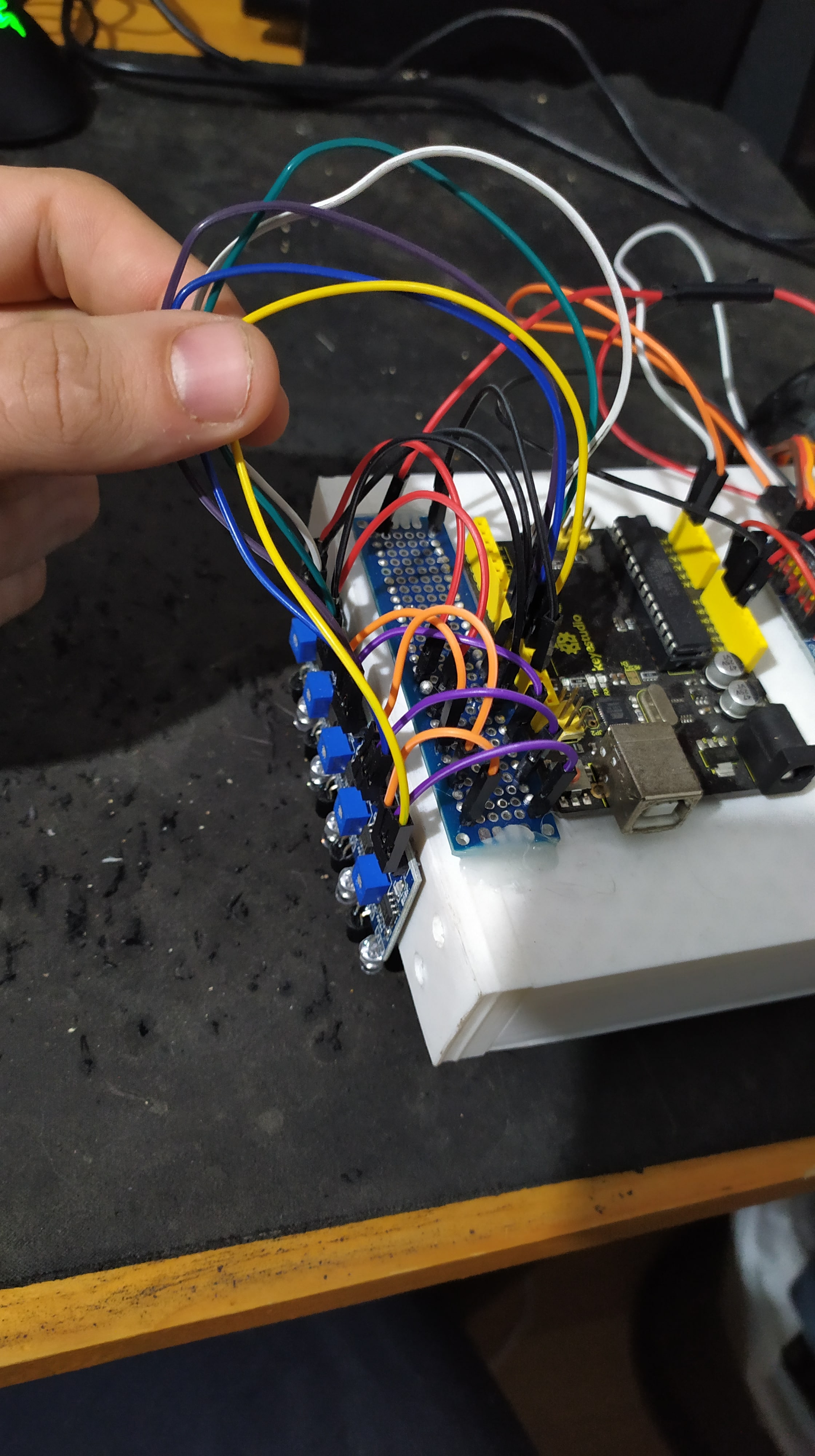
This is just a prototyping board with two lines connected, one for the positive and negative cables of the circuit.
To make the robot properly detect where the line is black, the sensors have to be calibrated with the potentiometer that is built in, turning it to where it just stops detecting the infrared light that is bounced back from the floor. Now, when it is on the floor, the light will come back and detect it as a 0, and when there is black tape, the light beam will not bounce, so a 1 will be read by the sensor.
And with this, the robot is finally asembled!
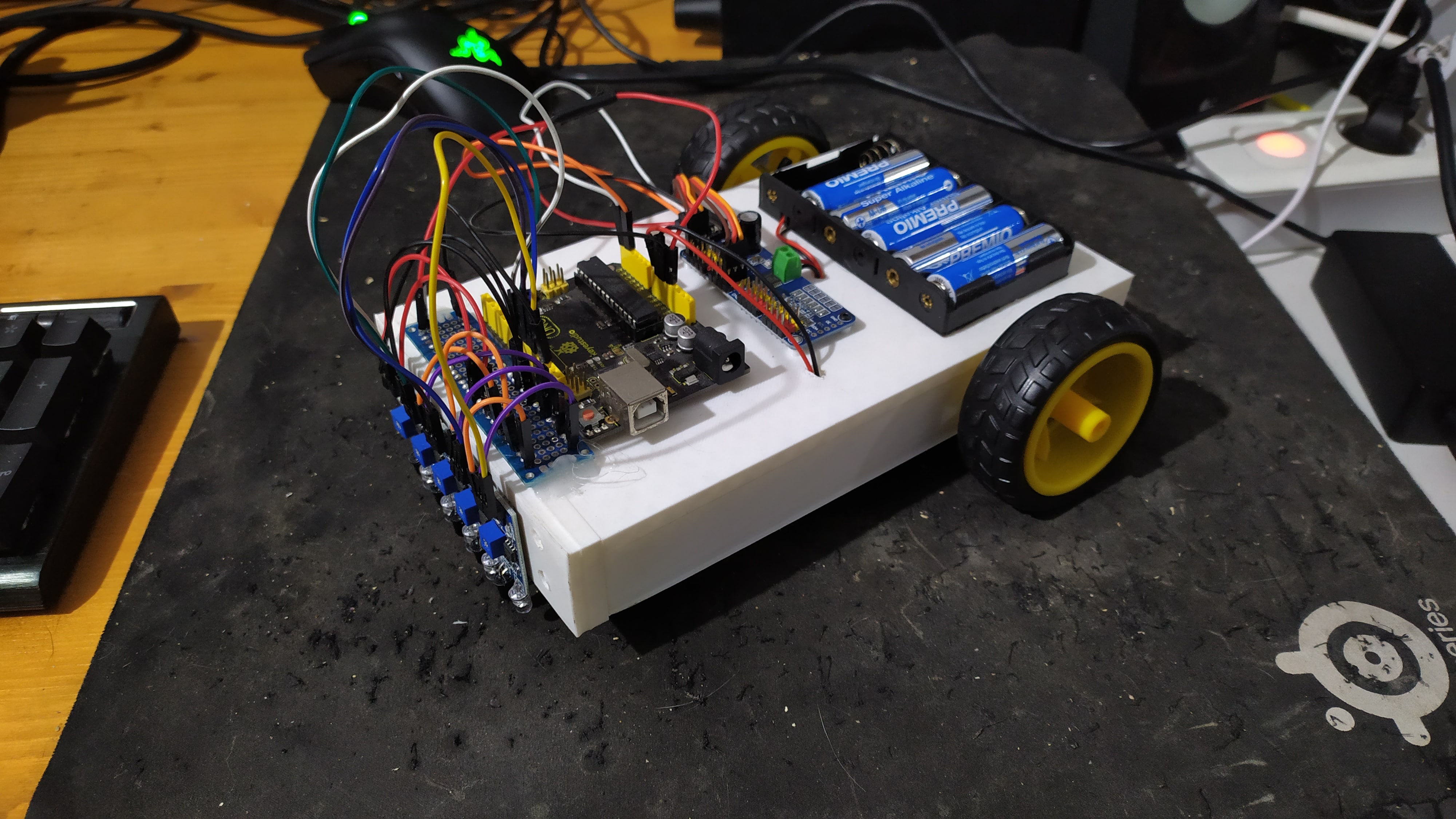
Im so sorry for the cable management.
Software
The software is very basic, since I wanted to build something that worked properly without having to worry much about other aspects, but you can see on the last section of the post for some ideas and improvements that I have on my mind.
The sensors are read and then, given it’s current values, a movement is decided: move forward if we are on the end (a black square), move forward if the line is detected on the centered sensor or either turn left or right if the sensors read the black line.
The first time I tried the code, as I had written it, the movement was quite exagerated and it oved the robot out of the path. After some tweeks, I tried again and:
Voilá. A basic line following robot! Lets give it a more complex path:
Ok, now to something actually new, lets try to cross lines and see what happens:
You can see how more complex situations require a more fine code to work properly. I tried to modify it and although I accomplished some improvement, it didn’t fully worked:
I didn’t want to spend more time on this project, so I decided to let it be as it is now and on future iterations of the robot I will try to improve it. This obstacle, for example, could be avoided by, instead of stopping fully on black lines, if it moved a little bit more to check if it is, indeed, the final square, and if not to keep moving forward.
Conclusions and further improvements
This project took me more than what I thought since I had little to no experience on many of the steps that were part of the whole process, and also because I’ve had less time available that what I thought that I will have. So this is another project that has suffered the terrible desease that is bad estimation.
However, I’ve learn so much that I’m really pleased of what I have accomplished and I’m looking forward into my next project, which I want to be now more focused on the intelligence part of the robot. I’m looking either into a rover or a robotic arm, and I will this time follow an open source design which I will build, so I can then focus on the software and control.
Some improvements / ideas that I have about the robot are:
-
Improve the smoothness of the movement.
-
Try to make the robot faster/more accurate by improving the software control.
-
I want to try and replace the basic software that I made with a proper architecture following the reactive paradigm, and try to accomplish the same task using behaviors and perceptual schemas. This will allow me to implement some of the theoretical knowledge that I’ve obtained reading “Introduction to AI Robotics” by Robin R.Murphy [3].
-
Design and print a new front plate to use other sensors, and reuse almost every other part on a different project (such as use some sonars or a camera)
-
Improve the cable management and make it look more clean, because aesthetics are always important.
References
-
[1] Warren, J., Adams, J., & Molle, H. (2011). Arduino Robotics. Apress.
-
[3] Murphy, R. R. (2019). Introduction to AI Robotics, Second Edition (2nd ed.). Bradford Book.